 |
1、Background:
|
| With the promotion of smart grid, smart meters will be applied in more and more ranges. Electronic single phase energy meter is mainly used by low-end & low-cost user. |
| |
2、system overview
|
|
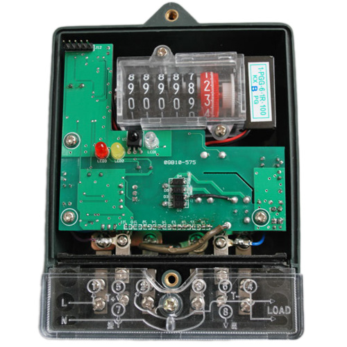
Electronic single phase energy meter is designed with MB95F204 and special energy measurement chip ADE7755 . With advantages of few components, simple construction, high reliability, low power and long service life, it can be used in measuring single phase A.C. active energy consumption at 50Hz.
It can realize remote meter reading by RS485 communication or carrier wave communication.Register display can show the history consumption electricity,The user can read and modify the parameter of the energy meter by IR communication with special equipment,.when power off,the energy meter can store the necessary data in RAM to EEPROM.
|
| |
3、H/W implementation explanation
|
 |
- a) Energy consumption measurement
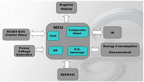
The AD7755 is a high accuracy electrical energy measurement IC which is intended for use with two-wire distribution systems. The AD7755 supplies Average Real Power information on the low frequency outputs F1 and F2. These logic outputs may be used to directly drive an electromechanical counter or interface to an MCU. The CF logic output gives instantaneous real power information.
- b) Register display
Drive by the IOs,display the Average Real Power information.
- c) RS485 or Carrer wave communication
we can use RS485 or carrier wave communication for remote meter reading.
- d) IR communication
we can use IR handset to read or modify some parameters
|
| |
4、S/W implementation explanation
|
| Software of Electronic single phase energy meter is composed of eeprom_driver.c,i2c.c,main.c,signal_stream.c,sys_timer_driver.c,system.c. |
- a) Main.c
- Initialize the MCU and energy meter data
- Detecting the system voltage ,if it is lower than standard level, store the data to EEPROM;if it is higher than the standard level, give warning sign.
- Calculate the power information and save it to EEPROM in case of necessary.
- Register display
- Deal with the RS485 or IR communication data.
- b) Eeprom_driver.c
The function of external Eeprom reading and writing.
- c) I2c.c
The function of I2C bus reading and writing is for EEPROM
- d) Signal_stream.c
- The receiving and sending function of RS485 communication
- Receiving the command from RS485 and deal with it .
- The receiving and sending function of IR communication
- Receiving the command from IR and deal with it .
- e) Sys_timer_driver.c
Operation of Software real timer clock
- f) System.c
- Initialization of EEPROM,detecting the warning signs,store the value of power consumption
- taking count of the pulse of power output from AD7755,store the data to EEPROM.
- Driving the register display
- Detecting the sampling voltage with AD In case of lower than 7.5v ,store the number of pulses to EEPROM. In case of higher than 15v,taking the warning LED light.Waiting until the sampling voltage to 7v
|
|